(With additional optional fix at the bottom of this page)
| Parts I used |
| 3 - #6 / 32 TPI Nylon setscrews - Part # NCS-632025-25 - Pack of 25 - SmallParts.com |
| .0625" (1/16") "O" Ring rope - Part # ORBK-01 - sold in bulk in 1 Foot quantities - SmallParts.com |
| #6 / 32 Tap and Drill Bit set |
| Aluminum Foil |
| Phillips Head Screwdriver |
| Knife |
| Black Sharpie Pen |
|
|
|
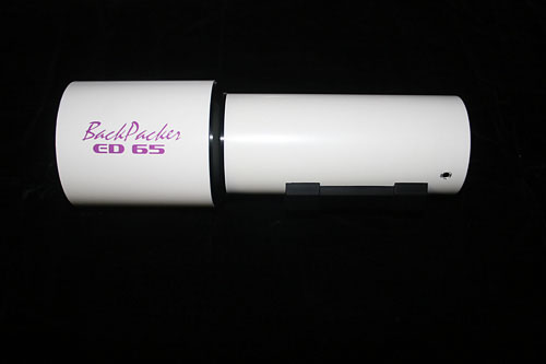
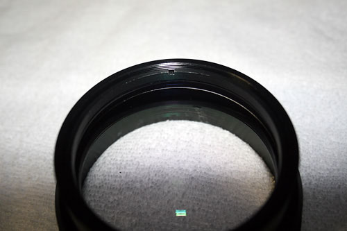
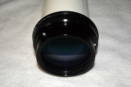
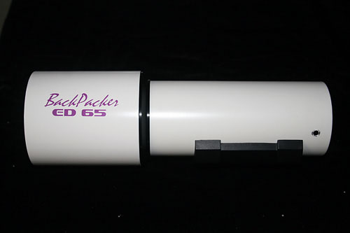
| This is the Burgess Optical ED65 Backpacker Special as I received it from Burgess Optical. | With the Lens Hood removed, you can access the 3 screws and remove them to release the lens cell. |
|
|
|
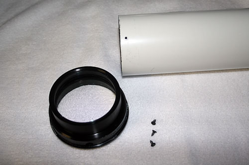
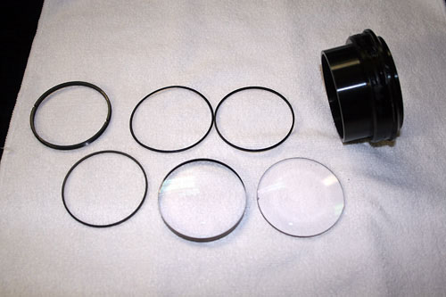
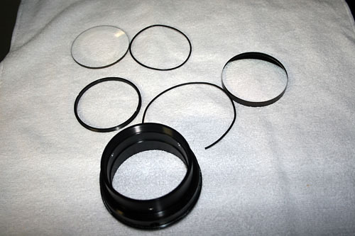
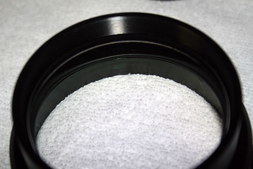
| The front of the lens cell has a slotted retaining ring. Just put your fingers, or fingernails, into the slots and gently turn the ring counterclockwise to remove it. If you have the tool that is made for this function, by all means, use it. | These are the parts in order, as they come out of the cell. From left to right, they are the slotted retaining ring, front metal spacer, the rubber "O" ring, the front element, the middle metal spacer, the rear element, and the cell body. |
|
|
|
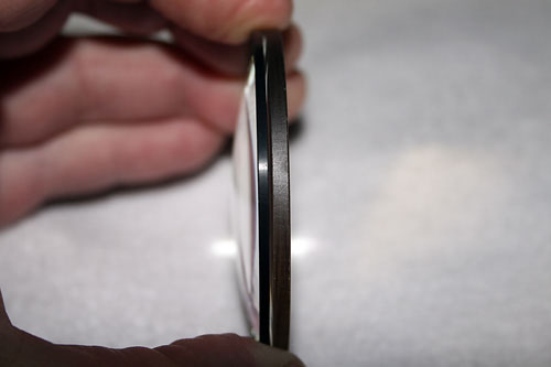
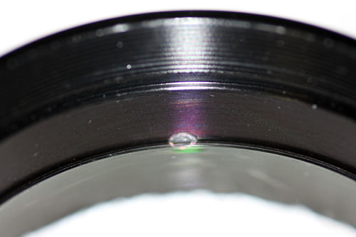
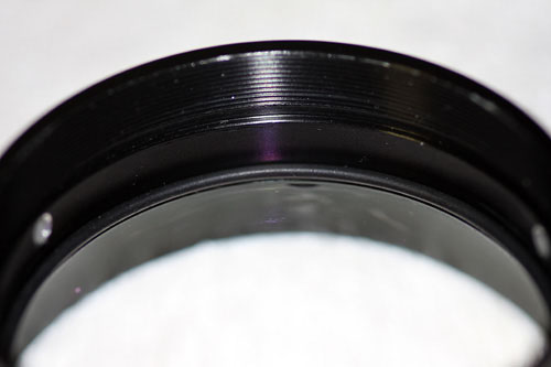
| I wanted to show this view so you can see the problem with the middle metal spacer. The rear element front curve is so steep that the spacer does not seat on it properly, leaving a small space. | Using the .0625" rubber ring rope, the two elements will seat better and slightly closer, solving some of the collimation and optical problems. The rubber rope is slightly thinner than the spacer. |
|
|
|
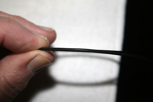
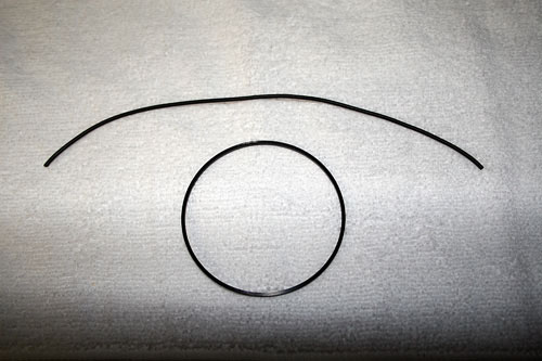
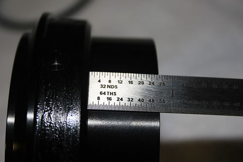
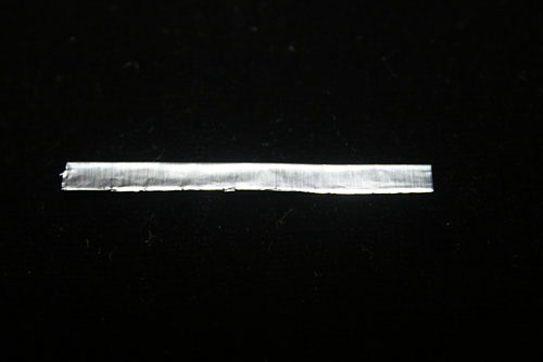
| The rubber "O" ring rope is at the top, and the middle metal spacer is on the bottom. The rubber "O" ring material replacing the metal spacer should be just over 8.25 inches long for a proper fit. | The outer front body of the cell is 27/32's wide. The inner front body of the cell to the shoulder that the rear element seats is 28/32's wide. |
|
|
|
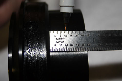
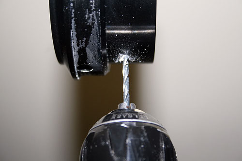
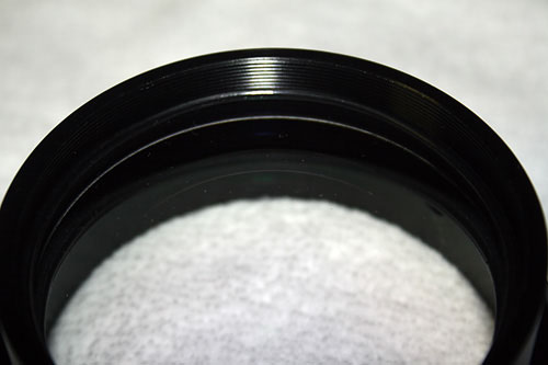
| To place the collimation setscrews for the front element, you need to measure 3/8" from the outer shoulder of the cell, and mark it. I lined these marks up with the holes that mount the cell to the scope body, as these are already 120 degrees apart. | Using a #36 drill bit, I drilled the 3 marked holes for the setscrews. |
 |
 |
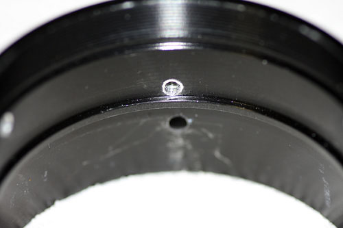
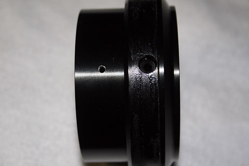
| This shows the hole for the set screw in line with the cell mounting hole. | Using a #6 / 32TPI tap and some cutting oil on the tap, I tapped the holes for the setscrews. |
|
|
|
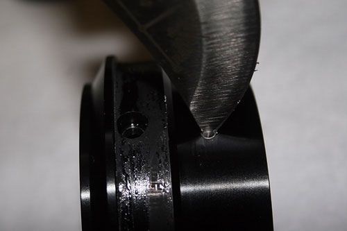
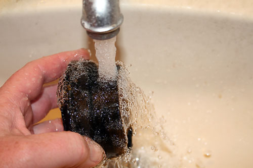
| I used a large knife to remove the burrs from around the holes, inside and outside the cell body. | After I was satisfied that the holes were deburred and flush, I washed the cell to remove the cutting oil and and shavings. |
 |
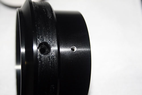 |
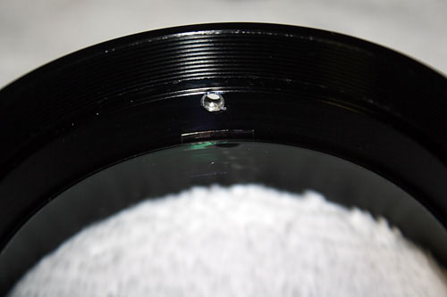
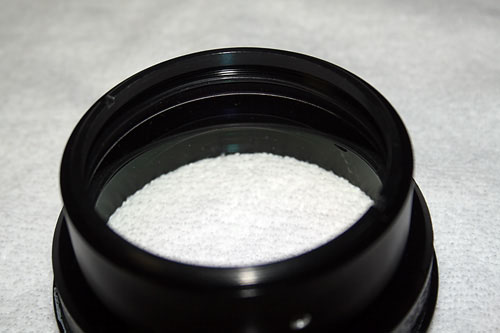
| With the cell dry, parts are gathered to prepare for reassembly. | Here is the tapped setscrew collimation hole. |
|
|
|
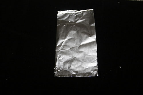
| These are the nylon collimation setscrews. I trim their length down a couple of threads to reduce their profile above the cell body. | For the shims on the rear element, I use aluminum foil. I used a standard, generic aluminum foil, not a heavy duty foil. You may have to add or remove a fold or two to get the proper thickness with your brand of foil. |
 |
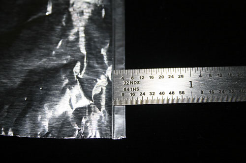 |
| I start the fold on the aluminum foil using a straightedge, I make it 1/8 inch wide. | I fold the foil to achieve 5 thicknesses of foil, then cut the folded foil from the sheet. |
 |
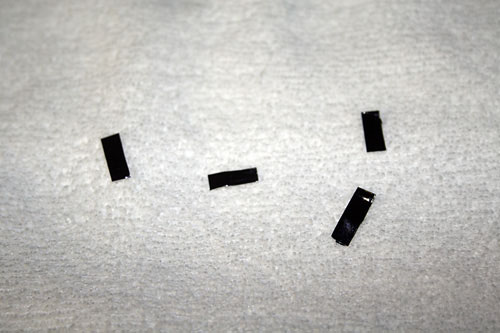 |
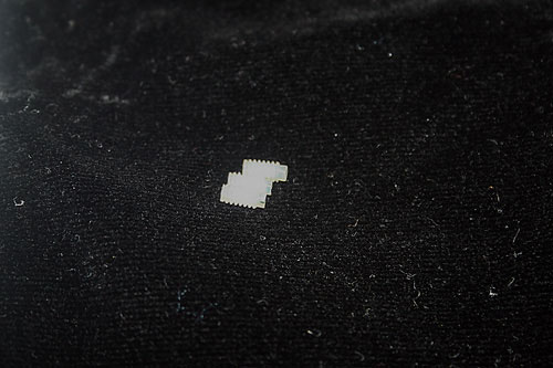
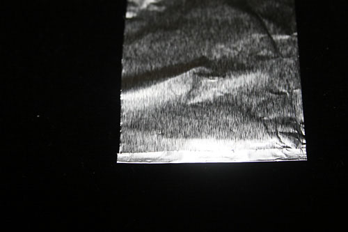
| This is the foil strip before I blacken it with a Sharpie pen to eliminate reflections. Allow the blackened foil to dry. | I cut the blackened foil strip into 4 parts. I will only use 3, but I like to have an extra if one of the tabs collapses while being put in place. |
 |
 |
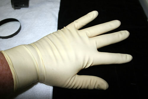
| I don surgical gloves for the rest of the procedures to eliminate the chance of contaminating the lens surfaces. | Here you can see the rear element in place, with the black foil tab between the cell wall and the rear element, right under the setscrew hole. I put these tabs at 120 degree spacing under the setscrew holes. The first one slides in easy. The second is tougher, and the last one can be a real pain. be patient and work slowly. |
 |
 |
| After the tabs are in place, I seat the "O" ring rope around the top of the rear element. It is replacing the metal spacer. | The front element drops in next. As long as you removed the burrs from the inside on the setscrew holes properly, it should drop right in with a bit of play in the cell. The rubber "O" ring goes in on top of the front element. |
 |
 |
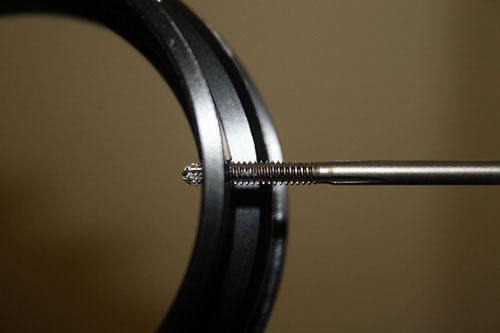
| Then you place the front spacer over the rubber "O" ring. This front spacer keeps the rubber ring from twisting or distorting when you screw on the retaining ring. The slotted retaining ring goes on last. Take your time and thread it properly. Use your finger or fingernails to tighten it down on the rubber "O" ring, but not too tight. Remember, the front element has to move a bit for collimation. | I insert the nylon setscrews and run them in until they stop. Once all of the setscrews are in, the scope will be ready for collimation. |
 |
 |
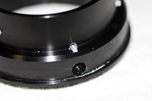
| Mount the cell back onto the body with the original screws. Be careful not to overtighten the screws and strip out the holes. You can see 2 of the 3 collimation screws in this image. | Here it is, ready for a focuser. |
Additional optional fix for cells that will not collimate
Some people have said that they cannot collimate their scopes using the fix above. The problem is that they cannot move the front element far enough in relation to the fixed rear element. This optional fix allows the rear element to move, allowing more offset to the front element, thereby adding the possibility of a better collimation. This added fix is a bit more work, but can help a difficult scope. If, no matter what you do when collimating your ED65, you cannot get rid of the flare off of a star, this fix could be your answer. .
|
|
|
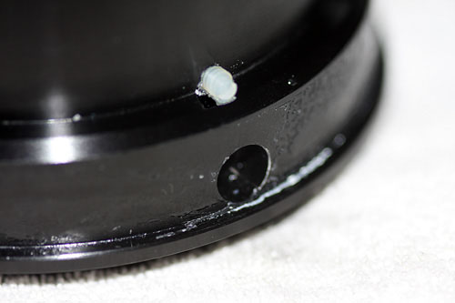
| Using the #6 drill, drill 3 holes 120 degrees apart, just like the holes for the fron element. This time, drill the holes right above the outside ledge. This will position the adjustment screws to contact the rear element. | Use the Tap to thread the holes for the #6/32TPI Nylon setscrews. This tap will angle itself downward slightly while you tap the threads. This is fine, as it will angle the setscrews slightly downward. |
 |
 |
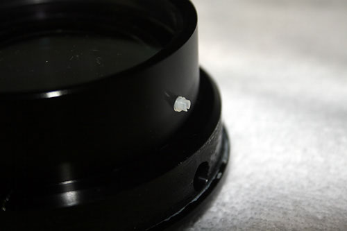
| With the rear element in place, you can see how the setscrew will contact the rear element. The hole is covered by the rear element a bit more than this shot shows, due to the clarity of the edge of the element. | When the rubber ring between the front and rear elements is put into place, the setscrew hole is completely covered. This will allow the rear element to be moved, as opposed to fixed in place with the use of shims. |
|
|
|
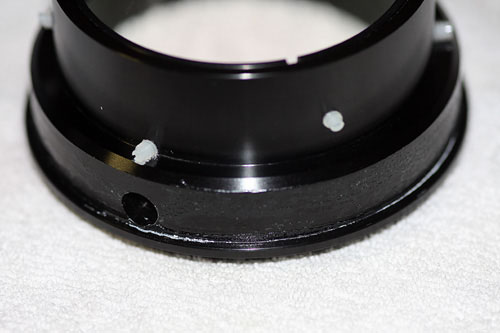
| Here is the rear element collimation setscrew in place. | Here you can see the upper, front element, setscrews and the lower, rear element, setscrews. I left the rear element collimation setscrews at full length so they are proud of the surface more, to aid in collimating in the dark. |
This page was last updated on April 27, 2008